
PID in Multirotors
In this extract, I will demonstrate how I used the PID (Proportional Integral and Differential) algorithm to induce balance on a single axis between two motors. I will also present the many phases I went through to get my final product.
Before we go any further, let’s evaluate the different methods that we could implement in order to achieve a state of balance. For now, the only two methods that concern us is the PID approach and the LQR approach. Both of these are closed loop systems and both involve an error and a setpoint or desired value.
I found the PID approach to be easier to implement than the LQR approach hence, we will be using the PID algorithm for this project. Nevertheless I have provided a brief description of LQR below.
LQR (Linear Quadratic Regulator), in simple terms, focuses on minimizing the cost/loss function (error) and does so by predicting the future based on past experiences. LQR is able to accomplish this by using a series of equations you can learn more about here and here.
On the other hand PID (in my opinion) is much more simple as I’ll discuss below.
PID Theory

It is a closed loop system that adjusts it’s output in order to get closer to the desired value.
The PID controller has various applications; for example, a thermostat may use it to either raise or lower the temperature based on the setpoint the user inputted. Similarly we will be using the algorithm to control the roll of the quadcopter.
The PID algorithm combines three different functions together: Proportional, Integral and Derivative as mentioned earlier. Each factor is multiplied by the error (which is the actual input subtracted by the setpoint/desired value) before being summed together.
// here is what it might look like for a quadcopter program int error; int angle; //derived from the accelerometer real time input int setpoint = 0; // assuming that the sensor is perfectly positioned, we want the angle between the quad arms and the axis to be 0 void loop(){ error = angle - setpoint; }After we find the error, we need to create an appropriate response. We do this by summing up the P, I and D functions…
P- the proportional function is basically the p term (kp) x error so the correction will be kp x error. If kp = 1, the correction will = error.
I- the integral term is used to correct an offset and may affect the rate in which the error may be corrected. If you increase ki, you will get a faster reaction nevertheless, you should keep it at a small value to prevent overshooting. To learn more about the I term click here
D- the derivative term is used to predict the future by using input collected over the time the program has been running. It determines how fast the error is changing and adjusts the correction based on this.
int error; int last_error; float kp; float ki; float kd; float proportional; float integral; float derivative; float correction; int thrust = 1200; Servo motor_1; // we classify our brushless motors as a Servo object in order to control them. Servo motor_2; float pwm_1; float pwm_2; void setup(){ motor_1.writeMicroseconds(1000); //we need to initiate the motors first motor_2.writeMicroseconds(1000); delay (5000); } void loop(){ time = millis(); proportional = kp*error; integral = integral + (ki*error); derivative = kd*((error - last_error)/time)); correction = proportional + integral + derivative; pwm_1 = thrust + correction; pwm_2 = thrust - correction; motor_1.writeMicroseconds(pwm_1); motor_2.writeMicroseconds(pwm_2); error = last_error; }The code above is not complete and needs other things too. I just simply illustrated what the PID might look like for a quadcopter. Now you can always just use the Arduino PID Library. However, I found it easier to do everything manually. If you wish to see the full code please e-mail me at ashbotic@gmail.com…
Now you need to set the values of kp, ki and kd. To achieve the perfect values, you will have to go through a process called PID tuning. The reason we need to do this is to make sure that the algorithm does not overcorrect itself and that it is performing at its best. For example, when kp = 2.5 and all the other terms = 0 the quadcopter will begin to oscillate and the algorithm will continue to overcorrect itself because the correction is basically the error x 2.5. I demonstrate this in the video. Check out the link on PID tuning as well to learn more about what each term does to the quadcopter.
Setup / Layout
If you are interested in doing a project similar to this, here are some parts that I used:
 DJI 420 Lite ESCs
 Arduino Mega
 Quad Arms
 DJI Motors and Props (2312e)
 Battery Pack for Arduino
 MPU-6050 & Potentiometer
 Power Supply
Future Aims
I hope to later further this project such that I can allow a quadcopter to balance on not one but both axis. I am already working on it and hope to provide an update later on…
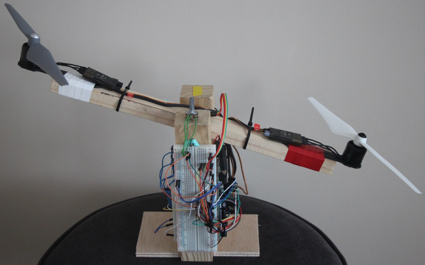
Here’s a little sneak peek of the setup I have going on:


